- مرشح المياه
· ترشيح المياه :
تعتبر عملية ترشيح المياه من العمليات المهمة التي تهدف إلى إزالة الجسيمات العالقة، والأملاح المعدنية، والكائنات الحية الدقيقة، وغيرها من ملوثات المياه، التي تسبب مشكلات صحية، وأمراضًا عديدة للإنسان .وتستخدم لهذا الغرض مرشحات يمكنها حجز الشوائب، (إما على سطح المرشح أو في وسطه) أو ترسيبها في الفراغات الموجود بين حبيبات معينة في وسط المرشح.
وتستخدم في صنع هذه المرشحات مواد عديدة مثل :
رمل السليكات، وفحم الأنثراسيت والألمنيت، كما يستخدم الكربون الحبيبي لإزالة طعم المياه ورائحتها غير المقبولين .

· مرشح الماء :
يمكنك أن تصنع مرشحًا يقوم بتنقية الماء بكفاءة عالية كالآتى :
1- أحضر مقصًّا، وزجاجة من البلاستيك، ودورقًا، وبعض القطن، وبعض القطع الصغيرة من البلور الصخرى، والحصى، ورملاً، وترابًا، وبعض الماء غير النقى .
2- اقطع الجزء السفلى من الزجاجة البلاستيك .
3- اقلب الزجاجة لتجعل فوهتها لأسفل .
4- أدخل كمية قطن فى فوهة الزجاجة، بارتفاع 1 سم .
1- املأ الزجاجة بكميات متتالية من البلور الصخرى، ثم الحصى، ثم الرمل، ثم التراب .
6- ضع الزجاجة بحيث تكون فوهتها إلى أسفل داخل الدورق .
7- اسكب الماء غير النقى داخل الزجاجة، ولاحظ ماذا يحدث له ؟
نلاحظ أن الماء قد أخذ وقتًا حتى تخلل من بين طبقات المرشح المتتابعة، حتى وصل فى النهاية إلى الدورق ماءً نقيًّا صالحًا للشرب .


الأحد، 2 سبتمبر 2012
مرشح المياه.
سرالضوء العجيب.
- سر الضوء العجيب
- أحضر بعض البذور، وطبقين، وبعض الطمي أو القطن .
2- ضع الطمي في كلا الطبقين بالتساوي، ثم اغرس البذور في ذلك الطمي جيدًا .
3- ضع قليلاً من الماء في كلا الطبقين . 4- ضع أحد الطبقين في ضوء الشمس، والآخر في مكان مظلم .
5- اترك الطبقين أسبوعًا، ثم ابدأ في ملاحظة ما طرأ عليهما من تغيير .

ماذا تلاحظ ؟
بعد أسبوع نلاحظ أن البذور في الطبق الأول قد نمت، وأصبحت نباتات صغيرة خضراء قوية، أما البذور في الطبق الثاني فقد نمت وأصبحت نباتات ضعيفة صفراء، لا تلبث أن تموت .
إن السر في ذلك يكمن في ضوء الشمس !! فهو يحتوى على الطاقة الضوئية التي تستقبلها المادة الخضراء الموجودة في ورق النبات، وبواسطة هذه الطاقة مع الماء الذي يمتصه النبات من التربة، وغاز ثاني أكسيد الكربون من الجو يقوم النبات بعملية البناء الضوئي، تلك العملية التي يستفيد فيها النبات بضوء الشمس في بناء المواد الغذائية اللازمة لحياته؛ لذا كان النبات الذي تعرض لأشعة الشمس قويًّا يافعًا أخضر اللون، على عكس النبات الآخر الذي لم يتعرض لضوء الشمس، وبالتالي لم تتم عملية البناء الضوئي، ومن ثم لم يتكون الغذاء، وكان نتيجة ذلك أن النباتات نمت صفراء ضعيفة هزيلة .
تسارع السيارة بعد إضاءة إشارة المرور.
تسارع السيارة بعد إضاءة إشارة المرور ( صورة متحركة )
بسم الله الرحمن الرحيمالسلام عليكم ورحمة الله وبركاته
السيارة الحمراء توضح تسارع السيارة بعد إضاء إشارةالمرور.........

الحركه الدائريه وانواع القوى المركزيه.
الحركه الدائريه وانواع القوى المركزيه
الجسم المتحرك في مسار دائري يكتسب تسارعا مركزيا بسبب اختلاف اتجاه سرعته ، و حسب قانون نيوتن الثاني [ الجسم يكتسب تسارع إذا أثرت عليه قوة ] ، فإن القوة المسببة لهذا التسارع المركزي هي ( القوة الجاذبة المركزية ) ، ويكون اتجاه القوة الجاذبة المركزية دائما نحو مركز الدائرة .
ملاحظة :
تختلف القوة الجاذبة المركزية بأختلاف الحركة الدائرية ، فإذا حرّكنا حجرا مربوطا بخيط في مسار دائري فإن القوة الجاذبة المركزية هي قوة الشدّ في الخيط .
وفي حالة الحركة الدائرية للقمر حول الأرض فإن القوة الجاذبة المركزية هي قوة التجاذب الكتلي .
و في حالة حركة الألكترون حول النواة فإن قوة الجاذبة المركزية هي قوة التجاذب الكهربائي .
وفي حالة حركة سيارة في مسار دائري فإن القوة الجاذبة المركزية هي قوة الأحتكاك السكوني بين أطارات السيارة و الطريق .


Interference of light waves.
Interference in light Waves
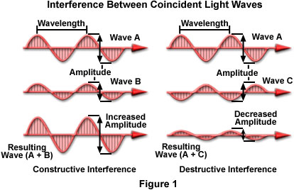
Lightwaves reinforce or neutralize each other in very much the same way as sound waves. If, for example, two lightwaves each of one color (monochromatic waves), of the same amplitude, and of the same frequency are combined, the Interference they exhibit is characterized by so-called fringes—a series of light bands (resulting from reinforcement) alternating with dark bands (caused by neutralization). Such a pattern is formed either by light passing through two narrow slits and being diffracted (see diffraction), or by light passing through a single slit. In the case of two slits, each slit acts as a light source, producing two sets of waves that may combine or cancel depending upon their phase relationship. In the case of a single slit, each point within the slit acts as a light source. In all cases, for lightwaves to demonstrate such behavior, they must emanate from the same source; light from distinct sources has too many random differences to permit Interference patterns.
The relative positions of light and dark lines depend upon the wavelength of the light, among other factors. Thus, if white light, which is made up of all colors, is used instead of monochromatic light, bands of color are formed because each color, or wavelength, is reinforced at a different position. This fact is utilized in the diffraction grating, which forms a spectrum by diffraction and Interference of a beam of light incident on it. Newton's rings also are the result of the Interference of light. They are formed concentrically around the point of contact between a glass plate and a slightly convex lens set upon it or between two lenses pressed together; they consist of bright rings separated by dark ones when monochromatic light is used, or of alternate spectrum-colored and black rings when white light is used. Various natural phenomena are the result of interference, e.g., the colors appearing in soap bubbles and the iridescence of mother-of-pearl and other substances.
Interferometers
Combining light rays to increase telescopic resolution
In 1801, the British physicist Thomas Young demonstrated that light propagates as waves, like waves on the surface of water. Young understood that when two light waves meet, they interact with each other. Scientists call this “interference”.

For example, if the crests (or troughs) of two light waves are coincident, they combine together to create an amplified wave in what is known as constructive interference.

In the opposite scenario, where the crests of one wave are aligned with the troughs of another, they cancel each other out and the light disappears. This is destructive interference.
Between these two extremes lie an infinite number of variations in which crests and troughs combine together to intensify or dim the light. In 1867, the French physicist Armand Hippolyte Louis Fizeau proposed that the resolution of telescopes could be improved if the collected light signals were allowed to combine with each other via constructive interference. Unfortunately, the technology of the day did not permit him to construct an instrument capable of combining light waves as they emerged from a telescope.
The arrival of such an instrument would have to wait until 1891 when Albert Abraham Michelson, an American physicist, constructed the first interferometer. Michelson used his new instrument to determine the diameter of Jupiter’s satellites. During the next sixty years, most studies in interferometry centred on the same type of work, such as measuring the diameter of a particular star, or determining the distance between the two suns in a double-star system.
In 1920, the American astronomer John August Anderson performed the first interferometric measurements on an object outside of our solar system when he determined the orbit of the double star Betelgeuse (Alpha Orionis). That same year, the American astronomers Albert Abraham Michelson and Francis Gladheim Pease were the first to measure the diameter of a star other than the Sun by using interferometry. The star in question was again the giant Betelgeuse.
In 1946, the British radio astronomer Martin Ryle, with the help of the physicist Derek D. Vonberg, constructed the first interferometer that could operate in the domain of radio waves. This breakthrough allowed the two scientists to discover many new celestial objects.
In 1956, the British physicists and astronomers Robert Hanbury Brown and Richard Quintin Twiss perfected their first interferometer using separate telescopes. Operating in the visible light domain, their instrument was tested on several types of stars and the resolution of the images were unequalled by any other imaging method in existence. The sharpness of the visible details in a normal image is limited by the diffraction of light waves as they pass through the telescope’s objective. Although larger objectives produce less diffraction and sharper images, it is very difficult to design objectives that are several tens of metres in diameter – the size required to significantly reduce diffraction. It was for this reason that the design by Brown and Twiss used separate telescopes. Acting together, the two instruments simulated one very large telescope, thus minimizing diffraction and maximizing image resolution.
During the late 1960’s and early 1970’s, the arrival of more powerful computers made interferometry increasingly accessible to researchers.
In 1967, a group of nine Canadian researchers – led by the astronomer J. L. (Allen) Yen of the University of Toronto – jointly used the 46-metre radio telescope of the Algonquin Radio Observatory in Ontario, and the 26-metre radio telescope of the Dominion Radio Astrophysical Observatory in British Columbia, to simulate a giant radio telescope measuring 3,074 kilometres in diameter (the distance separating the two observatories). It was the first successful long-distance interferometry experiment ever conducted.
In 1974, under the guidance of the American physicist (and future Nobel Laureate) Charles Hard Townes at the University Columbia in New York City, students Michael Allan Johnson, Albert L. Betz and Edmund Charles Sutton constructed the first infrared interferometer.


That same year, the French astronomer Antoine Émile Henry Labeyrie developed the first interferometer that could operate in real time. Prior to Labeyrie’s breakthrough, radiometric data was recorded on magnetic ribbon and sent to a laboratory to be processed.
Today, images with very high resolution are obtained using interferometers. Local celestial objects have the greatest scientific potential and represent the best targets
Lightwaves reinforce or neutralize each other in very much the same way as sound waves. If, for example, two lightwaves each of one color (monochromatic waves), of the same amplitude, and of the same frequency are combined, the Interference they exhibit is characterized by so-called fringes—a series of light bands (resulting from reinforcement) alternating with dark bands (caused by neutralization). Such a pattern is formed either by light passing through two narrow slits and being diffracted (see diffraction), or by light passing through a single slit. In the case of two slits, each slit acts as a light source, producing two sets of waves that may combine or cancel depending upon their phase relationship. In the case of a single slit, each point within the slit acts as a light source. In all cases, for lightwaves to demonstrate such behavior, they must emanate from the same source; light from distinct sources has too many random differences to permit Interference patterns.
The relative positions of light and dark lines depend upon the wavelength of the light, among other factors. Thus, if white light, which is made up of all colors, is used instead of monochromatic light, bands of color are formed because each color, or wavelength, is reinforced at a different position. This fact is utilized in the diffraction grating, which forms a spectrum by diffraction and Interference of a beam of light incident on it. Newton's rings also are the result of the Interference of light. They are formed concentrically around the point of contact between a glass plate and a slightly convex lens set upon it or between two lenses pressed together; they consist of bright rings separated by dark ones when monochromatic light is used, or of alternate spectrum-colored and black rings when white light is used. Various natural phenomena are the result of interference, e.g., the colors appearing in soap bubbles and the iridescence of mother-of-pearl and other substances.
Interferometers
Combining light rays to increase telescopic resolution
In 1801, the British physicist Thomas Young demonstrated that light propagates as waves, like waves on the surface of water. Young understood that when two light waves meet, they interact with each other. Scientists call this “interference”.
For example, if the crests (or troughs) of two light waves are coincident, they combine together to create an amplified wave in what is known as constructive interference.
In the opposite scenario, where the crests of one wave are aligned with the troughs of another, they cancel each other out and the light disappears. This is destructive interference.
Between these two extremes lie an infinite number of variations in which crests and troughs combine together to intensify or dim the light.
In 1867, the French physicist Armand Hippolyte Louis Fizeau proposed that the resolution of telescopes could be improved if the collected light signals were allowed to combine with each other via constructive interference. Unfortunately, the technology of the day did not permit him to construct an instrument capable of combining light waves as they emerged from a telescope.The arrival of such an instrument would have to wait until 1891 when Albert Abraham Michelson, an American physicist, constructed the first interferometer. Michelson used his new instrument to determine the diameter of Jupiter’s satellites.
During the next sixty years, most studies in interferometry centred on the same type of work, such as measuring the diameter of a particular star, or determining the distance between the two suns in a double-star system. In 1920, the American astronomer John August Anderson performed the first interferometric measurements on an object outside of our solar system when he determined the orbit of the double star Betelgeuse (Alpha Orionis). That same year, the American astronomers Albert Abraham Michelson and Francis Gladheim Pease were the first to measure the diameter of a star other than the Sun by using interferometry. The star in question was again the giant Betelgeuse.
In 1946, the British radio astronomer Martin Ryle, with the help of the physicist Derek D. Vonberg, constructed the first interferometer that could operate in the domain of radio waves. This breakthrough allowed the two scientists to discover many new celestial objects.
In 1956, the British physicists and astronomers Robert Hanbury Brown and Richard Quintin Twiss perfected their first interferometer using separate telescopes. Operating in the visible light domain, their instrument was tested on several types of stars and the resolution of the images were unequalled by any other imaging method in existence.
The sharpness of the visible details in a normal image is limited by the diffraction of light waves as they pass through the telescope’s objective. Although larger objectives produce less diffraction and sharper images, it is very difficult to design objectives that are several tens of metres in diameter – the size required to significantly reduce diffraction. It was for this reason that the design by Brown and Twiss used separate telescopes. Acting together, the two instruments simulated one very large telescope, thus minimizing diffraction and maximizing image resolution. During the late 1960’s and early 1970’s, the arrival of more powerful computers made interferometry increasingly accessible to researchers.
In 1967, a group of nine Canadian researchers – led by the astronomer J. L. (Allen) Yen of the University of Toronto – jointly used the 46-metre radio telescope of the Algonquin Radio Observatory in Ontario, and the 26-metre radio telescope of the Dominion Radio Astrophysical Observatory in British Columbia, to simulate a giant radio telescope measuring 3,074 kilometres in diameter (the distance separating the two observatories). It was the first successful long-distance interferometry experiment ever conducted.
In 1974, under the guidance of the American physicist (and future Nobel Laureate) Charles Hard Townes at the University Columbia in New York City, students Michael Allan Johnson, Albert L. Betz and Edmund Charles Sutton constructed the first infrared interferometer.
That same year, the French astronomer Antoine Émile Henry Labeyrie developed the first interferometer that could operate in real time. Prior to Labeyrie’s breakthrough, radiometric data was recorded on magnetic ribbon and sent to a laboratory to be processed.
Today, images with very high resolution are obtained using interferometers. Local celestial objects have the greatest scientific potential and represent the best targets
طاقة المادة.
والأنتقال من مكان إلى أخر في هذا الكون
بفضل أي قوة وطاقة تعوم الأرض في هذا الكون وتدور حول الشمس
وما هذه الطاقة التي لا تنفذ من المادة
أنها طاقة المادة الشحنات المغناطيسية المتماسكة في ذرات المادة
وهي موجودة في ذرات كل مادة وتختلف المادة من مادة إلى أخرى وبذلك تختلف
ذرات المادة من مادة إلى أخرى ويختلف عدد تواجد الشحنات وكيفيتها في الذرة
من ذرت مادة إلى أخرى
وفي القطعة المغناطيسية نجد أن هذه الشحنات تتماسك بكثافة مع بعضها البعض في
ذرات المادة وخارجها لتكون تلك القوة والطاقة وذلك المجال المغناطيسي لتلك
المادة في الفراغ وعند دخول مادة في مجال جذب تلك المادة ستنجذب أليها وبهذا
فأن المسؤول عن الجذب هو الشحنات المغناطيسية المتماسة بكثافة في الفراغ
والجذب هو عملية سحب الشحنات المغناطيسية الموجودة في مادة إلى مادة
مغناطيسية أخرى وبذلك تنجذب تلك المادة وهذا مايحدث في مجال جذب الكورة
الأرضية لكل مادة والكثير من المواد المنجذبة على سطح الأرض هي غير
متماسكة معها مغناطيسيا ولكنها منجذبة لقطعة مغناطيسية فقط
والتنافر هو خاصية مابين قطعتين مغناطيسيتين فقط
والأرض تعوم في هذا الكون بفضل قوتها وطاقتها المغناطيسية ولو كان هذا الكون
فراغ لما ستطاعت الأرض أن تبقى عائمة في الفراغ ولكن هنلك قوة وطاقة
مغناطيسية هائلة في هذا الكون تحافظ على بقاء الأرض وكواكب المجموعة
الشمسية عائمة في هذا الكون وهذا يثبت لنا أن طاقة المادة الطاقة المغناطيسية
هي التي تملاء الفراغ في هذا الكون وهل الحرارة الضوء الصوت الموجات
الكهرومغناطيسية تمتد وتنتشر مخترقتا المجال المغناطيسي للأرض ولهذا الكون
أو أنها تنتقل بواسطة طاقة المادة الطاقة المغناطيسية
الأنتقال في هذا الكون من مكان إلى مكان لأي شيء يتطلب طاقة وطاقة المادة
الطاقة المغناطيسية تملاء الفراغ في هذا الكون وبأمكاننا تحويل الطاقة من طاقة
إلى طاقة وتنتقل الطاقة بواسطة الطاقة أيظا
الحرارة الضوء الصوت الموجات الكهرومغناطيسية وجد أنها تتشارك في الأنتقال
بشيء واحد وهو طاقة المادة الطاقة المغناطيسية وهي الشحنات المغناطيسية
المتماسكة مع بعضها البعض بكثافة والتي تملاء الفراغ في هذا الكون
وهي واسطة الأنتقال في هذا الكون
ومن الشحنات المتماسكة في الفراغ تمكنا من توليد الطاقة الكهربائية
وهو تحويل الطاقة المغناطيسية إلى طاقة كهربائية بواسطة الطاقة الحركية
والتيار الكهربائي هو مرور سيل من الشحنات المغناطيسية في سلك وهذا السيل
مصيره العودة إلى الأرض لتكمل بذلك الدائرة الكهربائية التي نستفيد منها ويتم
توليد الطاقة الكهربائية بواسطة السرعة العالية لقطعة مغناطيسية تدور داخل ملف
فيتم أختطاف الشحنات المغناطيسية لتمر بذلك السلك
ومن هذا نستنتج
أولا أنه هنلك مقاومة من القطعة المغناطيسية لسرعة الدوران
وثانيا أن المغناطيس يعوض مايفتقده من الشحنات
ومن هذا المفهوم عن القطعة المغناطيسية
أننا لو أردنا أختطاف شحنات من المجال المغناطيسي فأنه هنالك قوة رد فعل
وستنادا على هذا فأننا نستطيع الحركة في هذا الكون
مستندين على أختطاف الشحنات المغناطيسية المتماسكة في هذا الكون فأن ردت
الفعل ستكون حركتنا في هذا الكون وبسرعة عالية
ملاحظة أن وزن الجسم صفر خارج مجال الغلاف الجوي للأرض وفي هذا الكون
وأن قام ذلك الجسم بأختطاف الشحنات المتماسكة والممسكة به في ذلك المجال من
احدا جهاته ستكون ردت الفعل حركته في ذلك الأتجاه وسيكون لهذه المركبة ذيل
من بخار الماء وسنتمكن من النضر أليها من الأرض عندما تبداء الأبحار في هذا
الكون سيكون أنجازا علميا وسياسيا وسنتمكن من معرفة الكثير في هذا الكون
خواص المتجهات Properties of Vectors.
جمع المتجهات Vector addition
يمكن جمع المتجهات التي تعبر عن كميات فيزيائية متشابهة مثل جمع متجهيين للقوة، ولكن لا يمكن ان نجمع متجه قوة مع متجة سرعة.
لجمع متجه A مع متجه B تكون المحصلة المتجه R
(R= A + B---> (1.5
هذه القاعده بشكل عام : ولكنها تختلف تباعاً لموقع المتجهين المراد جمعهما بالنسبة لبعضهما .
1) أول حالة : عندما يكونان متوازيين :
. Two vectors, A and B are equal if they have the same magnitude and direction, regardless of whether they have the same initial points, as shown in
.
إذاً في هذه الحالة المقدار : R=|A|×|B
وإتجاهها نفس إتجاه A&B
Panel 2 #2 A vector having the same magnitude as A but in the opposite direction to A is denoted by -A , as
.
هنا المحصلة تساوي الصفر . لأنهما متساويين في المقدار .
متعاكسين في الإتجاه .
R=A-B
B= -A:.
R=A-A=0<=
يمكن جمع المتجهات التي تعبر عن كميات فيزيائية متشابهة مثل جمع متجهيين للقوة، ولكن لا يمكن ان نجمع متجه قوة مع متجة سرعة.
لجمع متجه A مع متجه B تكون المحصلة المتجه R
(R= A + B---> (1.5
هذه القاعده بشكل عام : ولكنها تختلف تباعاً لموقع المتجهين المراد جمعهما بالنسبة لبعضهما .
1) أول حالة : عندما يكونان متوازيين :
. Two vectors, A and B are equal if they have the same magnitude and direction, regardless of whether they have the same initial points, as shown in
.
إذاً في هذه الحالة المقدار : R=|A|×|B
وإتجاهها نفس إتجاه A&B
Panel 2
#2 A vector having the same magnitude as A but in the opposite direction to A is denoted by -A , as .
هنا المحصلة تساوي الصفر . لأنهما متساويين في المقدار .
متعاكسين في الإتجاه .
R=A-B
B= -A:.
R=A-A=0<=
2) الحالة الخاصة الثانية لجمع المتجهات : هي عندما تكون متتابعة .
.
The sum of two vectors, A and B, is a vector C, which is obtained by placing the initial point of B on the final point of A, and then drawing a line from the initial point of A to the final point of B
A+B = C
والـمتجهه C هنا( المحصلة ) هو طول الضلع الذي يغلق الشكل .
ويكون إتجاهه بإتجاه رأس السهم للمتجه المجاور .
الذي أغلقنا المضلع عنده .
3)الحالة الثالثة لجمع المتجهات : عندما يكونان متقابليّ بالرأس .

Vector subtraction is defined in the following way. The difference of two vectors, A - B , is a vector C that is,
C=A - B
(or C = A + (-B .
Thus vector subtraction can be represented as a vector addition.
يعني : المحصلة هنا تساوي حاصل طرح المتجهين أو حاصل جمعهما مع مراعاة الإشارة لإتجاهيهما .
..........
لاحظوا أن جميع المتجهات لها خاصية التبديل.
(A + B = B + A---> (1.6

The sum of two vectors, A and B, is a vector C, which is obtained by placing the initial point of B on the final point of A, and then drawing a line from the initial point of A to the final point of B
A+B = C
والـمتجهه C هنا( المحصلة ) هو طول الضلع الذي يغلق الشكل .
ويكون إتجاهه بإتجاه رأس السهم للمتجه المجاور .
الذي أغلقنا المضلع عنده .
3)الحالة الثالثة لجمع المتجهات : عندما يكونان متقابليّ بالرأس .
Vector subtraction is defined in the following way. The difference of two vectors, A - B , is a vector C that is,
C=A - B
(or C = A + (-B .
Thus vector subtraction can be represented as a vector addition.
يعني : المحصلة هنا تساوي حاصل طرح المتجهين أو حاصل جمعهما مع مراعاة الإشارة لإتجاهيهما .
..........
لاحظوا أن جميع المتجهات لها خاصية التبديل.
(A + B = B + A---> (1.6
الاشتراك في:
التعليقات (Atom)